Virtual Realitifying my real climbing wall, part 3
Alignment part 1: Uniform scaling.

I spend my nights buried in neon lights and code, delivering cutting-edge genetics data to data scientist. I love exploring the latest advancements in technology and genetics with my cat by my side.
The lines between human and machine have blurred, and technology has augmented many aspects of our lives. I believe in the power of technology to make the world a better place, and I'm excited to be a part of this ever-evolving field.
If you've read the introductory blog, then you know this post is the third in a series of steps of for aligning a virtual 3D model with the real world, you know, for fun and profit.
In the last blog we had a nice 3d scan of the room we want to align, my home climbing wall.
For this section, you'll need to get an Oculus Inegration project going in Unity with an OVR Camera Rig. It doesn't take long to set up and there are tutorials everywhere. Import your 3d model, too.
Alignment issues
My earliest experiences were using AR Kit on Android. This uses QR codes or image references. However, this doesn't translate to the Quest 2 as there is no current access to the camera feed ( also a problem for foot tracking! ).
The solution I settled on was one of using four reference points, two in the real world and two on the virtual model.
Setting up the model reference points
The idea is that two reference points are placed on the model at some specific location, then the user has to place the other two reference points at the corresponding real world locations, using the Quest 2's Passthrough mode.
Let's do it...
The first step is to create an empty gameobject that will contain the 3d model and it's reference points, name it ParentContainer or something. This is the gameobject we will apply our transformations to. Inside that gameobject, place the 3d model and create two basic spheres and scale them to a reasonable size. 0.05 works for me. Rename the spheres ModelReferenceA and ModelReferenceB. Remove any colliders from the spheres, we don't need them.
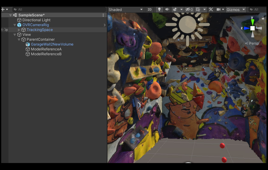
Set ModelRefA at 0,0,0. For this we'll move the 3d model to the reference points rather than the ref to the model. Having ModelRefA at 0,0,0 makes all the transformations easier on my brain which doesn't like dealing with rotation offsets.
So, with ModelRefA at 0,0,0 you can move the 3d model until ModelRefA is on the point you want to use as your first reference point. I chose the corner of this orange triangle volume on the back wall.
For ModelReferenceB, this time move the actual sphere to the location of the second desired reference point, rather than moving the 3d model. I chose a the tip of a climbing hold at the opposite end of the wall to improve the accuracy of the scaling steps later on.
Great, our two model reference points are suitably positioned. If you have a play rotating the parentContainer object, everything will rotate around RefA.
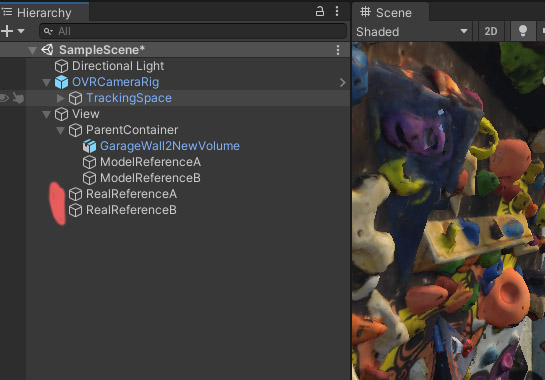
Creating and positioning the real world reference points
Now let's create two more spheres, called RealReferenceA and RealReferenceB, outside of the parentContainer object. The user will position these in physical space from within VR at the corresponding real world locations to the points we chose on the 3d model. The alignment script will then do it's thing to line up the two real reference points with those on our 3d model.
Initially, I used hand tracking and gesture detection to place the RealReference points. This allowed me to place my fingertip right on the correct point in the real world and give a thumbs up (with the other hand). The thumbs up gesture was detected and the reference point is placed at the tip of the index finger ( I followed these excellent Valem tutorials to set this up ). This worked really well, but I found it a bit of a faff to keep putting the controllers down to do the alignment and then picking them back up to interact with the control panel I have in my game.
I eventually replaced the gesture detection with just using the hand controllers and the Oculus LocalAvatar hand models. It was less accurate at first because the avatar model finger tip is not tracking your real finger tip. It didn't take long to get used to it, though, and after I few goes I could very accurately place the points in space.
The script for this is super duper simple. Create a gameobject to hold this script - I tend to drop stuff like this on a controller layer ( but I have an MVC background and have no idea if this is good practice in Unity ). For the rightFingerTipPosition transform, I used another sphere and made it a child of the RightControllerAnchor which is part of the OVRCameraRig. Then, from within VR in PlayMode move the sphere until it is at the position of your right finger tip, then copy the transform values, exit play mode and paste the values back on. Now you have a sphere which follows the finger tip of the LocalAvatar hand model. Anyway, the script...
public class AlignReferencePointsController : Monobehaviour
{
    public Transform rightFingerTipPosition;
    public GameObject RealReferenceA;
    public GameObject RealReferenceB;

    private void Update()
    {
            if (OVRInput.Get(OVRInput.Button.One))
            {
                AlignmentButtonADetected();
            }

            if (OVRInput.Get(OVRInput.Button.Two))
            {
                AlignmentButtonBDetected();
            }
    }

    public void AlignmentButtonADetected()
    {
            RealReferenceA.transform.position = rightFingerTipPosition.position;
    }

    public void AlignmentButtonBDetected()
    {
            RealReferenceB.transform.position = rightFingerTipPosition.position;
    }
}
As simple as that. Press button A and RealReferenceA will magically appear the location of the right index tip. Press button B, and RealReferenceB will do the same.
The wall alignment script
Everything else is left to a single script which has three methods, each called in sequence by one main method called AlignMyWall. I use the right hand trigger to call this method.
public GameObject realWorldRefA;
public GameObject realWorldRefB;

public GameObject parentContainer;
private GameObject modelRefA;
private GameObject modelRefB;

public void AlignMyWall()
{
        AlignFirstReferencePoint();
        ScaleModelToMatchRealReferenceDistance();
        RotateModelToMatchReferenceAlignment();
}
So, the first method here moves the whole parent container object to the location of RealReferenceA. Remember, we made sure that ModelReferenceA was at 0,0,0 so this method actually makes ModelReferenceA and RealReferenceA overlap at the same point in space.
private void AlignFirstReferencePoint()
{
       parentContainer.transform.position = realWorldRefA.transform.position;
}
Easy.
The second method gets the distance between RealReferenceA and RealReferenceB and compares it to the distance between ModelReferenceA and ModelReferenceB. The difference between these distances gives a ratio value that we can use to scale the parentContainer so that the distances match. Like so...
private void ScaleModelToMatchRealReferenceDistance()
{

    float distanceBetweenRealRefs = Vector3.Distance(realWorldRefA.transform.position, realWorldRefB.transform.position);

    float distanceBetweenModelRefs = Vector3.Distance(modelRefA.transform.position, modelRefB.transform.position);

    float distanceRatio = distanceBetweenRealRefs / distanceBetweenModelRefs;

    var x = parentContainer.transform.localScale.x;
    var y = parentContainer.transform.localScale.y;
    var z = parentContainer.transform.localScale.z;

    if (distanceBetweenModelRefs != distanceBetweenRealRefs)
    {
        parentContainer.transform.localScale = new Vector3(x * distanceRatio, y * distanceRatio, z * distanceRatio);
    }
}
Perfect the model is now scaled to match the real world. All that is left to do is rotate the model, there are two steps for this. The first is to rotate the model to match the direction of the vector between RealReferenceA and RealReferenceB. We can do that like this:
private void RotateModelToMatchReferenceAlignment()
{
    Vector3 realWorldRefsDirection = realWorldRefB.transform.position - realWorldRefA.transform.position;

    Vector3 modelRefsDirection = modelRefB.transform.position - modelRefA.transform.position;

    float angleBetweenVectors = Vector3.Angle(realWorldRefsDirection, modelRefsDirection);

    if (angleBetweenVectors != 0)
    {
        var deltaRotation = Quaternion.FromToRotation(modelRefsDirection, realWorldRefsDirection);
        parentContainer.transform.rotation *= deltaRotation;
    }
}
The second rotation step is to rotate the model around an Axis which runs between RefA and B. I ended up doing this manually, using the joystick on the controller to call the function below.
public void RotateAroundAlignmentAxis(float speed)
 {
        Vector3 axis = realWorldRefB.transform.position - realWorldRefA.transform.position;

        // rotate around point A, perpendicular to axis AB.
        parentContainer.transform.RotateAround(realWorldRefA.transform.position, axis, speed);

 }
and that's it, the model can now be aligned!
NOTE: You'll obviously need to enable Passthrough mode to enable you to see the real world from within the headset, and this only works when the app is compiled to the headset (i.e. not from play mode), but that is covered elsewhere. Basically there are 4 steps.
- Check 'Passthrough capability enable' from the OVRCameraRig General Features in the inspector.
- Check Enable Passthrough beneath the mixed reality options.
- Add an OVR Passthrough layer script to the OVRCameraRig and select Underlay as the placement type.
- Get rid of any skybox material from your scene.
This means I can't show passthrough in my preview videos either to demonstrate the alignment.
However, from playmode you can still place the two reference points and scale the model. I like to do this to create a tiny version of my 3d model that i can rotate and look around at as though is in a model on my desk. Like this:
This is how it all now works:
- Build the app to the Quest 2 headset
- Go into the room (In my case, my climbing wall)
- Fire up the app
- Walk up the the real world point that corresponds to ModelReferenceA, for me this is the tip of that orange triangle volume.
- Press A to place RealReferenceA on that spot
- Do the same for RealReference B by pressing B at the location of ModelReferenceB
- Trigger the alignmywall method. In the demo project I attached this to the right hand trigger.
- Lastly, use the joystick to rotate the model around it's orientation axis until it matches up.
TIP: Set the material of the 3d model to be about 30-40% transparent, so you can see the real wall and the 3d model are clearly aligned.
So, long story short... this get us 95% of the way…
The last 5%
What I found from all this is that the Metashape mesh is not perfect in terms of proportions. Specifically, the areas of the wall immediately around the reference points were always really accurate, but the further from the points you went, especially on the opposite wall, there was about 3 inches of mismatch.
It was ok, it was climbable. But, it wasn't perfect and that bothered me a lot. It stayed this way for months, and literally kept me awake.
More about the nailing down that last 5% using complex MeshDeformations in the next blog


